
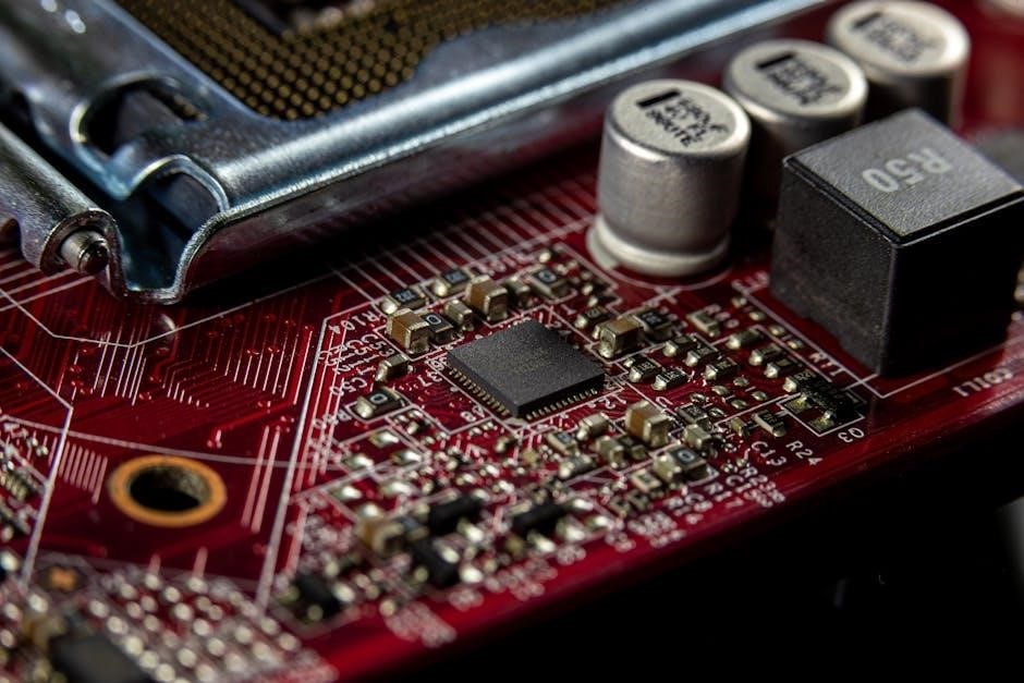
The 1E7G circuit‚ a single-tube regenerative receiver‚ offers a fascinating entry point into vintage radio technology. Its simplicity and performance‚ detailed in available PDF schematics‚ make it a popular project for enthusiasts.
Historical Context of 1E7G
The 1E7G circuit emerged during the golden age of radio‚ a period marked by rapid innovation in vacuum tube technology. Early radio experimentation‚ particularly in the 1920s and 30s‚ heavily relied on regenerative receivers due to their sensitivity and ability to operate with minimal components.
This design‚ often found documented in older radio handbooks and PDF schematics‚ represents a crucial step in the evolution of radio communication. Before the widespread availability of superheterodyne receivers‚ regeneration was a key technique for amplifying weak signals. The 1E7G‚ utilizing a single tube‚ became a popular choice for hobbyists and experimenters seeking an affordable and effective radio solution.
Its enduring appeal is evidenced by the continued interest and availability of information‚ including detailed circuit diagrams and construction guides‚ readily accessible online in PDF format. The circuit’s simplicity allows for easy understanding of fundamental radio principles.
Purpose and Applications of the Circuit
The primary purpose of the 1E7G circuit is to receive and amplify radio signals‚ specifically within the medium wave (AM) broadcast band‚ though modifications can extend its range. Its regenerative design allows for impressive sensitivity with a minimal component count‚ making it ideal for receiving distant stations. Detailed schematics‚ often found as PDF documents‚ illustrate its straightforward construction.
Historically‚ this circuit served as a cost-effective alternative to more complex receivers. Today‚ its applications are largely focused on educational purposes and the enjoyment of vintage radio technology. Hobbyists frequently build the 1E7G to learn about radio principles and experience the unique characteristics of regenerative reception.
The availability of comprehensive PDF guides facilitates reproduction and experimentation. It’s also used in projects demonstrating early radio techniques‚ offering a tangible connection to the history of communication. The circuit’s simplicity makes it a great starting point for beginners.

Core Components of the 1E7G Circuit
Essential components include the 1E7G vacuum tube‚ inductors (L1‚ L2) for tuning‚ and a variable capacitor (VC1) – all detailed in available PDF schematics.
The 1E7G Vacuum Tube: Characteristics and Function
The 1E7G is a triode vacuum tube specifically designed for RF amplification and oscillation in regenerative receiver circuits. Commonly found in vintage radio designs‚ its characteristics are crucial to the 1E7G circuit’s operation. PDF documentation reveals it operates with a filament voltage of 1.4V and a plate voltage typically between 25V and 50V‚ though experimentation within safe limits is common.
As a triode‚ the 1E7G controls current flow between the cathode and plate using the grid. In this circuit‚ it performs dual roles: amplifying weak radio signals and providing the necessary gain for regeneration. The tube’s amplification factor (mu) and plate resistance significantly impact the circuit’s sensitivity and stability. Understanding these parameters‚ as outlined in tube datasheets available in PDF format‚ is vital for successful construction and tuning. Proper biasing of the 1E7G is essential for optimal performance‚ ensuring it operates within its linear region to minimize distortion.
Inductors (L1‚ L2) and Their Role in Tuning
Inductors L1 and L2 are fundamental components in the 1E7G regenerative radio circuit‚ forming the resonant tank circuit alongside the variable capacitor (VC1). Their primary function is to selectively amplify signals within a specific frequency range. Circuit PDF schematics typically show these as wound on a ferrite core or air-wound‚ influencing their inductance value.
The inductance values of L1 and L2‚ in conjunction with VC1‚ determine the circuit’s resonant frequency; Adjusting VC1 changes the capacitance‚ shifting the resonant peak and allowing tuning across the desired frequency band (85-120MHz‚ as noted in project details). L2 often provides feedback to the grid‚ crucial for regeneration. Precise winding and placement of these inductors‚ detailed in construction guides found in PDFs‚ are vital for optimal performance and minimizing unwanted oscillations. Their quality factor (Q) impacts selectivity and sensitivity.
Variable Capacitor (VC1): Frequency Control
Variable Capacitor VC1 is the primary means of frequency selection in the 1E7G regenerative receiver. Working in tandem with inductors L1 and L2‚ it forms a resonant LC tank circuit. Detailed schematics‚ often available as PDF documents‚ illustrate its placement within the circuit. Adjusting VC1’s capacitance alters the resonant frequency‚ enabling the receiver to tune to different radio stations.
The capacitance range of VC1 dictates the tuning bandwidth. A larger capacitance range allows for broader tuning‚ while a smaller range provides finer control. The quality of VC1 is also critical; a high-quality capacitor minimizes losses and improves selectivity. Construction guides found in PDFs often recommend specific types of variable capacitors for optimal performance. Proper grounding and shielding of VC1 are essential to prevent unwanted oscillations and maintain circuit stability‚ as highlighted in various online resources.
Circuit Operation: A Detailed Explanation

The 1E7G operates by amplifying weak radio signals through positive feedback‚ controlled by regeneration. PDF guides detail how this creates oscillation and boosts sensitivity.
Oscillation Principles in Regenerative Receivers
Regenerative receivers‚ like the 1E7G‚ achieve amplification not just through direct gain‚ but by intentionally bringing the circuit close to oscillation. This is a crucial principle‚ explained thoroughly in available PDF documentation. The feedback loop‚ created by coupling a portion of the output signal back to the input‚ is carefully controlled.
When the feedback is weak‚ the signal is simply amplified. However‚ as feedback increases‚ the circuit approaches instability. At the brink of oscillation‚ even very weak signals can trigger sustained oscillations‚ dramatically increasing sensitivity. The 1E7G’s design‚ as shown in schematics within these PDFs‚ utilizes this principle.
This near-oscillation state isn’t desired for continuous operation‚ as it would distort the signal. Instead‚ the regeneration is adjusted to just below the point of oscillation‚ providing maximum amplification without unwanted distortion; Understanding this delicate balance is key to successfully operating and tuning a 1E7G receiver‚ and the PDF resources provide detailed guidance on achieving it.
Regeneration and its Impact on Sensitivity
Regeneration‚ central to the 1E7G’s operation‚ dramatically boosts sensitivity – the ability to detect weak signals. As detailed in numerous PDF guides‚ this isn’t simply amplification; it’s a clever exploitation of feedback. By feeding a portion of the output signal back to the input‚ the effective gain is multiplied. This is particularly vital for receiving distant or faint broadcasts.

However‚ increasing regeneration isn’t limitless. Beyond a certain point‚ the receiver will oscillate uncontrollably‚ producing a hissing sound. The sweet spot‚ carefully adjusted via a control knob‚ lies just below this oscillation threshold. This maximizes sensitivity without sacrificing signal clarity. PDF schematics often illustrate the critical components involved in regeneration control.
The 1E7G’s single-tube design makes this feedback mechanism particularly apparent. Understanding how regeneration affects signal strength and clarity‚ as explained in the available PDF resources‚ is crucial for optimal performance and successful tuning of this classic circuit.
The Role of Feedback in Amplification
In the 1E7G regenerative receiver‚ feedback isn’t a detrimental effect‚ but the principle of amplification. As detailed in readily available PDF documentation‚ a portion of the output signal is intentionally redirected back to the input of the vacuum tube. This creates a positive feedback loop‚ reinforcing the incoming signal;
This process dramatically increases the tube’s gain‚ allowing it to amplify even incredibly weak radio signals. Unlike standard amplification‚ the gain isn’t solely determined by the tube’s characteristics; it’s dynamically controlled by the amount of feedback applied. PDF schematics clearly show the feedback path‚ typically involving a tapped inductor.
However‚ careful control is essential. Excessive feedback leads to oscillation‚ rendering the receiver unusable. The 1E7G’s design incorporates a variable control to adjust the feedback level‚ allowing the operator to find the optimal balance between amplification and stability‚ as explained in numerous PDF guides.
1E7G Circuit Diagram Analysis
PDF schematics reveal a straightforward design: a single tube‚ tuned circuit‚ and feedback network. Understanding component placement and signal flow is key to grasping its operation.
Identifying Key Circuit Nodes
Analyzing the 1E7G circuit diagram (often found in PDF format) reveals several crucial nodes. The cathode of the 1E7G tube represents a primary grounding point and source of electron flow. The plate connection‚ leading to the tuned circuit (L1‚ L2‚ and VC1)‚ is where amplified RF signals emerge.
The grid‚ acting as the control element‚ receives input signals and regulates plate current. The feedback tap‚ taken from the plate circuit and fed back to the grid‚ is vital for regeneration. Identifying the junction of L2 and VC1 pinpoints the resonant frequency.
Furthermore‚ the positive high-tension (B+) supply node provides power‚ while the filament supply node heats the tube. Understanding the voltage levels at each node‚ as detailed in schematic PDFs‚ is essential for troubleshooting and optimization. Careful tracing of signal paths from antenna to output helps pinpoint potential issues.
Signal Flow and Path Analysis
Tracing the signal path in the 1E7G circuit (detailed in available PDF schematics) begins with the antenna‚ coupling RF energy to the tuned circuit (L1‚ L2‚ and VC1). This resonant circuit selectively amplifies desired frequencies. The amplified signal then reaches the 1E7G tube’s grid‚ modulating the plate current.
The plate current variation‚ representing the amplified signal‚ flows through the plate load and feedback network. A portion of this signal is fed back to the grid‚ initiating regeneration. This feedback loop dramatically increases sensitivity. The output signal is then taken from the plate circuit‚ often through a coupling capacitor.
PDF diagrams illustrate how adjustments to VC1 tune the resonant frequency‚ while the feedback control adjusts regeneration. Understanding this flow‚ and potential signal losses at each stage‚ is crucial for optimizing performance. Analyzing the path reveals how small changes impact overall reception.
Understanding Component Interconnections
The 1E7G circuit’s functionality hinges on precise component interconnections‚ clearly depicted in readily available PDF schematics. The antenna connects to the tuned circuit (L1‚ L2‚ and VC1)‚ establishing the initial RF input. This tuned circuit’s output feeds the 1E7G tube’s grid‚ controlling its amplification.
Crucially‚ the plate circuit includes a feedback path – a resistor or coil – returning a portion of the output signal to the grid. This feedback is vital for regeneration. The plate load resistor defines the operating point‚ while the filament is directly connected to the power supply.
PDF resources highlight the importance of proper grounding‚ minimizing noise and ensuring stability. Understanding how each component interacts – the antenna‚ tube‚ tuned circuit‚ and feedback network – is essential for building and troubleshooting this classic regenerative receiver. Correct wiring is paramount for optimal performance.

Building and Testing the 1E7G Circuit
Construction relies on PDF schematics for accurate wiring. Testing involves powering the circuit and carefully adjusting regeneration for signal reception and optimal performance.
Component Sourcing and Selection
Sourcing components for the 1E7G regenerative radio‚ guided by available PDF schematics‚ requires careful consideration. The 1E7G vacuum tube itself can be found through vintage electronics suppliers or online auction sites‚ though availability varies.
Inductors (L1 & L2) are often hand-wound‚ utilizing enamel-coated copper wire‚ with specifications detailed in the schematics. Variable capacitors (VC1) can be salvaged from older radios or purchased new. Resistors and capacitors should be of appropriate voltage and tolerance ratings.
Component selection impacts performance; higher-quality capacitors generally offer better stability. Pay close attention to the tube’s datasheet for optimal operating parameters. Consider using a breadboard initially for prototyping before soldering permanent connections. Matching component values closely to the schematic is crucial for successful operation and achieving the desired frequency range.
Construction Techniques and Best Practices
Building the 1E7G‚ referencing a reliable PDF schematic‚ demands meticulous technique. Utilize a stable‚ grounded work surface to prevent static discharge; Short‚ direct wiring minimizes stray capacitance and improves stability.
Soldering should be clean and secure‚ avoiding cold joints. Employ a point-to-point wiring method‚ carefully following the schematic’s layout. Grounding is critical; a solid ground plane enhances performance and reduces noise.
Component placement matters – keep high-frequency components close together. Shielding sensitive areas can minimize interference. Use quality hook-up wire and ensure all connections are mechanically sound. Regularly check your work against the schematic during construction. A well-constructed circuit‚ based on the PDF‚ will yield optimal results and easier troubleshooting.
Testing Procedures and Troubleshooting
Initial testing of your 1E7G‚ guided by the PDF schematic‚ begins with voltage checks. Verify the correct B+ voltage is present at the tube socket. Slowly increase the regeneration control‚ listening for oscillations – a slight whistle indicates it’s working.
If no oscillations occur‚ check the tube‚ wiring‚ and component values. A weak signal might indicate low regeneration or improper tuning. Excessive regeneration leads to instability and screeching.
Troubleshooting often involves signal tracing with an oscilloscope or RF probe. Check for proper grounding and shielding. Consult the schematic for expected waveforms at key points. Remember safety precautions when working with live circuits. A systematic approach‚ referencing the PDF‚ will pinpoint and resolve most issues‚ ensuring optimal performance.

Advanced Considerations and Modifications
Exploring the 1E7G’s PDF reveals potential improvements. Experimenting with tube types and optimizing component values can enhance stability and sensitivity for superior performance.
Improving Stability and Reducing Noise
Achieving stable operation with the 1E7G regenerative receiver‚ as detailed in numerous PDF guides‚ requires careful attention to layout and component selection. A grounded grid cathode bypass capacitor is crucial for minimizing noise and preventing oscillations. Shielding the circuit‚ particularly the input and feedback paths‚ significantly reduces external interference.
Power supply filtering is paramount; a clean DC voltage is essential for low noise. Utilizing a regulated power supply‚ or adding extra filtering capacitors‚ can dramatically improve performance. The physical layout should minimize loop areas to reduce unwanted coupling.
Experimentation with different regeneration control methods‚ such as a trimmer capacitor in the feedback loop‚ allows for precise adjustment and improved stability. Proper grounding techniques‚ including a solid ground plane‚ are vital for minimizing hum and noise. Careful component placement and short lead lengths further contribute to a quieter receiver‚ enhancing its usability and enjoyment.
Optimizing Regeneration for Maximum Performance
Fine-tuning regeneration is key to unlocking the 1E7G’s potential‚ as illustrated in various PDF resources. The goal is to reach the point of maximum signal amplification without inducing instability or oscillation. A variable resistor in the feedback loop provides precise control over regeneration levels;
Carefully adjusting this control allows you to balance sensitivity and selectivity. Too little regeneration results in weak signals‚ while excessive regeneration leads to distortion and unwanted oscillations. Observing the signal strength and clarity while adjusting is crucial.
Experimentation with different feedback coil taps can also optimize performance for specific frequencies. The ideal regeneration setting will vary depending on signal strength and local interference. Mastering this adjustment‚ guided by available schematics‚ transforms the 1E7G from a basic receiver into a surprisingly capable performer‚ capable of pulling in weak signals.
Exploring Alternative Tube Options
While the 1E7G circuit traditionally employs a specific vacuum tube‚ experimentation with alternatives can yield interesting results‚ as discussed in several PDF guides. Tubes with similar characteristics – high gain and low plate resistance – are suitable candidates. The 1P29‚ for instance‚ is often cited as a viable substitute‚ offering comparable performance.
However‚ tube substitutions may necessitate minor component value adjustments to maintain optimal circuit operation. Specifically‚ changes to the plate resistor or feedback network might be required to compensate for variations in tube characteristics. Careful observation of the circuit’s behavior during these modifications is essential;
Exploring different tubes allows for tailoring the receiver’s performance to specific preferences or available components. Detailed schematics and understanding the circuit’s core principles‚ readily available in PDF format‚ are invaluable when venturing into tube substitutions‚ ensuring stable and efficient operation.

Resources and Further Learning
PDF schematics and online forums provide invaluable support for building and understanding the 1E7G circuit. Explore communities dedicated to regenerative radio for shared knowledge!
Relevant PDF Documents and Schematics
Numerous PDF documents detail the 1E7G regenerative radio circuit‚ offering varying levels of complexity and supplemental information. A key resource is often Raymond Haigh’s work‚ frequently cited within online communities dedicated to vintage radio restoration and construction. These schematics typically illustrate the complete circuit layout‚ component values‚ and wiring diagrams essential for replication;
Searching online archives and dedicated radio enthusiast websites will reveal a wealth of scanned original documentation. Pay attention to documents that include not only the schematic but also practical construction notes‚ tuning instructions‚ and troubleshooting guides. Variations exist‚ so comparing multiple schematics can help clarify ambiguities and identify potential improvements.
Furthermore‚ some PDFs include detailed explanations of the circuit’s operation‚ making them valuable learning tools. Look for documents that explain the function of each component and the principles behind regenerative amplification. Careful study of these resources is crucial for successful construction and operation of the 1E7G receiver.
Online Forums and Communities
Engaging with online forums and communities is invaluable when working with the 1E7G regenerative radio circuit. These platforms host a wealth of collective knowledge‚ offering assistance with component sourcing‚ construction techniques‚ and troubleshooting challenges. Many dedicated vintage radio forums feature specific threads discussing the 1E7G‚ often including shared experiences and modifications.
Active communities provide a space to ask questions‚ share progress‚ and receive feedback from experienced builders. Searching these forums for “1E7G” or “regenerative receiver” will quickly reveal relevant discussions and resources. Members frequently share links to PDF schematics and offer advice on optimizing performance.
Beyond dedicated radio forums‚ general electronics communities can also be helpful. Remember to clearly articulate your questions and provide detailed information about your build to receive the most effective assistance. Collaboration and knowledge sharing are key benefits of these online resources.
Books and Articles on Regenerative Radio
Delving into established literature on regenerative radio provides a strong theoretical foundation for understanding the 1E7G circuit. Several classic texts detail the principles of regeneration‚ feedback‚ and tuning‚ offering insights beyond basic schematics. These resources explain the underlying physics‚ aiding in troubleshooting and optimization efforts.
While dedicated books specifically on the 1E7G are rare‚ publications covering general radio receiver design often include sections on regenerative circuits. Look for titles focusing on vacuum tube technology and early radio construction. Articles in vintage radio magazines‚ often available in digitized formats or reprints‚ can provide practical building tips and variations on the basic 1E7G design.
Understanding the historical context and evolution of regenerative receivers enhances appreciation for the 1E7G’s ingenuity. Many resources also contain valuable PDF schematics and component information‚ complementing online resources.