
Gemini Security System Manual: Comprehensive Guide
Welcome! This manual details the Gemini system, a UL-listed security solution. It’s intended for professional installers and end-users, covering installation, programming (GEM-P3200), operation, and troubleshooting.
NAPCO Security Systems provides detailed instructions, referencing WI818 for programming. Remember to contact the installing company for service or support when needed.
The Gemini Security System represents a cutting-edge approach to safeguarding your property, blending robust protection with user-friendly operation. This system is designed for a diverse range of applications, from residential homes to commercial establishments, offering scalable security solutions tailored to specific needs. It’s a sophisticated system, but built with accessibility in mind.
This manual serves as a comprehensive guide, detailing every facet of the Gemini system – from initial setup and programming (specifically referencing the GEM-P3200 programming instructions, document WI818) to daily operation and troubleshooting. It’s crucial to understand that certain advanced programming functions, such as activating Fault Fine or Locate features, are intended exclusively for qualified professional installers.

The Gemini system boasts features like multiple arming modes (Away, Stay, Night), silent alarm capabilities, and detailed zone definitions for precise sensor placement. The system’s integration with daily astrological forecasts (Gemini horoscope) is a unique feature, offering a playful addition to your security experience. Remember, proper installation and adherence to UL listing standards are paramount for optimal performance and reliability. Always prioritize safety and consult a professional when needed.
System Components Overview
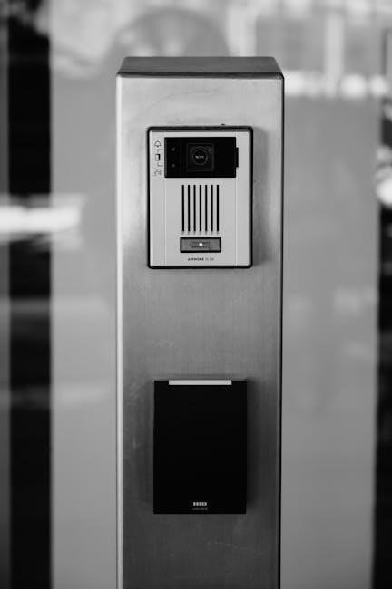
The Gemini Security System comprises several key components working in concert to provide comprehensive protection. Central to the system is the Control Panel, the brain of the operation, managing all sensors and communication. The Keypad serves as the primary user interface for arming, disarming, and programming the system, utilizing unique User Codes for authorized access.
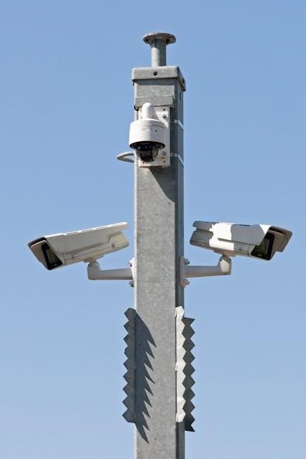
A network of Sensors – including door/window contacts, motion detectors, and Ultrasonic Sensors – detect potential intrusions. These sensors are strategically placed based on Zone Definitions to pinpoint the location of any security breach. The system also incorporates a Battery Backup, ensuring continued operation during power outages.
Furthermore, the Gemini system includes a built-in Sounder for audible alarms and status notifications. Professional installers utilize specific Wiring Diagrams and adhere to detailed Technical Specifications during installation. The system’s design prioritizes reliability and adherence to UL listing and security standards, ensuring a robust and dependable security solution. Proper component interaction is vital for optimal system performance.
Understanding the Control Panel
The Gemini Control Panel is the central hub, responsible for processing signals from all connected sensors and initiating appropriate responses. A crucial indicator is the STATUS light; a green light signifies a disarmed system, while an off state indicates an open zone requiring attention. The panel facilitates communication with monitoring stations and manages system events.
Programming of the control panel is primarily performed by qualified installers, utilizing the GEM-P3200 programming instructions (WI818). This includes defining Zone Definitions, setting Exit Time Configuration, and adjusting advanced settings. The panel also manages System Trouble Indicators, alerting installers to potential issues.
The panel’s internal components include a power supply, a communication module, and a processor. It supports various communication methods for alarm reporting. Understanding the panel’s functionality is key to effective system management. Remember, installers have access to advanced settings like Fault Fine Activation and the Locate Feature Activation for fine-tuning system performance.
Keypad Functions and Operation
The Gemini keypad serves as the primary interface for user interaction. Upon successful disarming, the system displays a READY status. To silence the keypad sounder during an alarm, press the C button. Entering a valid User Code followed by ‘A’ is crucial in high-security installations to acknowledge and address alarm events.
Keypad functions include arming and disarming the system, entering user codes, and acknowledging alarms. The keypad provides visual and audible feedback regarding system status. It’s essential to familiarize yourself with the specific button layout and their corresponding functions.
The keypad also allows for manual system resets for certain troubles, initiated with code ‘10’ (installer access only). Remember, attempting to Start Exit Time or Activate Fault Fine requires installer-level access (codes ‘11’ and ‘12’ respectively). Proper keypad operation is vital for maintaining system security and responding effectively to potential threats.
User Codes: Creation and Management
User Codes are fundamental to the Gemini system’s security. A valid User Code must be entered before acknowledging alarms, particularly in UL-listed or high-security setups, followed by the ‘A’ key. Proper code management is critical to prevent unauthorized access and maintain system integrity.
The GEM-P3200 programming instructions (WI818) detail the process for creating, modifying, and deleting user codes. Professional installers handle this process, ensuring each user receives a unique and secure code. It’s vital to avoid easily guessable codes like birthdays or addresses.
Regularly review and update user codes, especially when personnel changes occur. Limit the number of active user codes to only those who require access. Remember, compromised user codes represent a significant security vulnerability. The system’s programming interface allows for granular control over user access levels and permissions, enhancing overall security.
Arming and Disarming the System
The Gemini system offers multiple arming modes – Away, Stay, and Night – each tailored to different security needs. Arming activates the system’s sensors, triggering an alarm upon intrusion. Disarming deactivates these sensors, allowing authorized access.

To disarm, enter your valid User Code on the keypad. The system will respond with a “READY” indication if disarmed normally. However, following a silent alarm, the system will remain READY without any specific indication that an alarm was transmitted. Always verify the system status.
Initiating an alarm requires contacting the Fire Department from an outside phone line. After, press the ‘C’ button to silence the keypad sounder. If no fire is present, enter your User Code followed by the ‘J’ key to reset the system. Proper arming and disarming procedures are crucial for reliable security.
Arming Modes: Away, Stay, and Night
The Gemini system provides three distinct arming modes to suit varying occupancy scenarios. Away mode is activated when the premises are completely vacant, arming all sensors for comprehensive protection. Stay mode secures the perimeter – doors and windows – while allowing movement within the protected space, ideal for nighttime use.
Night mode functions similarly to Stay, but can be customized by the installer to include or exclude specific interior sensors. This allows for tailored security while occupants are present. Selecting the appropriate mode is vital for minimizing false alarms and maximizing security effectiveness.
Remember that activating any arming mode initiates sensor monitoring. Any breach of a protected zone will trigger an alarm response. Understanding the nuances of each mode ensures the Gemini system provides optimal protection based on your specific needs and occupancy status. Consult your installer for custom mode configurations.
Silent Alarm Operation

The Gemini system supports silent alarm transmission, crucial for discreet security breaches. When a silent alarm is triggered, the system transmits a signal to the monitoring station without activating audible alarms on the keypad. This is particularly useful in situations where alerting an intruder is undesirable.
Upon receiving a silent alarm signal, the monitoring station will attempt to verify the alarm and, if confirmed, dispatch emergency services – including the Fire Department from an outside phone line. The system will remain in a READY state, displaying no immediate indication of alarm transmission to anyone on-site.
To silence the keypad sounder after a silent alarm, press the C button. If no fire is evident, enter your valid User Code followed by the J button to reset. In UL-listed or high-security installations, a valid User Code must precede the A button for alarm reset confirmation.
Responding to Alarms
When the Gemini system alarm sounds, immediate action is required. First, prioritize personal safety. If a potential intrusion is suspected, do not confront the intruder. Instead, immediately contact the monitoring station to confirm the alarm and request dispatch of emergency services.
If the STATUS light is off, a zone is open, indicating the location of the alarm trigger. Secure the open zone if it’s safe to do so. Remember, a valid User Code followed by the A button is required to silence the alarm in UL-listed installations.
If a false alarm occurs, and you’ve verified it’s safe, enter your User Code and press the J button to reset the system. If you are unable to reset the system or determine the cause of the alarm, immediately contact the installing company for service. Do not attempt complex troubleshooting yourself; professional assistance is recommended.
Troubleshooting Common Issues
Gemini system malfunctions can often be resolved with simple checks. If the system fails to arm, ensure all zones are secure – doors and windows closed and properly secured. A green STATUS light indicates a fully secured system, while an off light signifies an open zone.
For trouble indicators, consult the System Trouble Indicators and Resetting section. Some troubles can be manually reset using code 10 (installer access only). If the keypad sounder is active, press the C button to silence it.
If experiencing persistent issues, avoid attempting complex repairs. Refer to the Wiring Diagrams and Technical Specifications for basic connectivity checks. Ultimately, contacting the installing company is crucial for professional diagnosis and repair. Remember, unauthorized tampering may void the warranty and compromise system security.
System Trouble Indicators and Resetting
The Gemini system utilizes various indicators to signal potential issues. A flashing light or specific beep patterns denote different trouble conditions. Consult the detailed system logs (accessible via professional programming) for precise error codes. Common troubles include low battery, communication failure, and zone faults.
Some troubles can be manually reset. Enter code 10 on the keypad – this is an installer-only function and should not be used by end-users unless specifically instructed. This resets certain system flags, but doesn’t address underlying hardware problems.
For persistent trouble indicators, or if unsure about the reset procedure, call the installing company for service. Attempting unauthorized resets can disrupt system functionality. Regular maintenance, including battery checks, can prevent many trouble conditions. Always prioritize professional assistance for complex issues.
Zone Definitions and Sensor Placement
Gemini security zones represent distinct areas of protection within your property. Proper zone definition is crucial for accurate alarm reporting and efficient response. Each sensor (door, window, motion detector, etc.) is assigned to a specific zone during system programming.
Ultrasonic sensors require strategic placement. Install them on the top of windshield pillars, ensuring they face towards the center of the rear window, avoiding air vents. This maximizes coverage and minimizes false alarms. Door and window sensors should be mounted securely, aligned correctly, and tested after installation.
Careful sensor placement minimizes vulnerabilities. Consider potential entry points and adjust zone configurations accordingly. A green STATUS light being off indicates an open zone – immediately secure the area. Professional installers will optimize zone definitions based on your property’s layout and security needs.
Ultrasonic Sensor Installation Guidelines
Gemini ultrasonic sensors provide a robust layer of interior protection, detecting movement within vehicles. Successful installation hinges on precise placement and adherence to these guidelines. Prioritize mounting sensors on the upper portion of windshield internal pillars – this offers optimal coverage and stability.
Crucially, direct the sensor’s field of view towards the center of the rear window. Avoid positioning sensors near air vents, as airflow can trigger false alarms. Before final mounting, with the alarm system disarmed, roll down a front window slightly to test sensor functionality and range.
Ensure a secure attachment to prevent dislodgement. Proper alignment is vital; misaligned sensors may experience reduced sensitivity or create blind spots. Regularly inspect sensors for obstructions or damage. Professional installation is recommended for optimal performance and to avoid compromising the system’s integrity.
Programming Instructions (Professional Installers)
Professional installers, refer to the accompanying GEM-P3200 Programming Instructions (WI818) for comprehensive details. These instructions detail the system’s advanced configuration options, requiring specialized knowledge and access codes. Incorrect programming can compromise system functionality and security.
Key programming areas include zone definitions, user code management, and alarm response settings. Installers can adjust system sensitivity, configure arming modes (Away, Stay, Night), and customize fault handling. Access to advanced settings, such as exit time configuration, fault fine activation, and the Locate feature, is restricted to authorized personnel.
Important: Manual system trouble resets (option 10) and activation of features like Exit Time (option 11) and Fault Fine (option 12) are installer-exclusive functions. Always document all programming changes for future reference and troubleshooting. Ensure all programming adheres to UL listing requirements and local security standards.
GEM-P3200 Programming Details
The GEM-P3200 programming interface allows granular control over system behavior. Access requires a valid installer code. Zone programming defines sensor types (door, window, motion) and their associated responses to alarm triggers. User code management includes creating, deleting, and modifying individual user access levels and permissions.
Critical settings include entry/exit delay times, adjustable to accommodate user needs and prevent false alarms. Alarm verification options can be configured to reduce nuisance calls. The system supports various communication protocols for central station monitoring, requiring appropriate configuration parameters.
Advanced options encompass battery testing schedules, low battery alerts, and tamper protection settings. Programming also dictates the system’s response to power outages and communication failures. Thoroughly review all settings and test the system after any programming changes to ensure proper functionality and adherence to security protocols. Refer to WI818 for detailed parameter lists.
Advanced System Settings (Installers Only)
Access to these settings requires a valid installer code. Incorrect modification can compromise system security and functionality. Fault Fine Activation (option 12) adjusts sensitivity to minimize false alarms, but requires careful calibration per zone. Locate Feature Activation (option 13) enables remote zone identification during an alarm event, aiding dispatchers.
Exit Time Configuration (option 11) allows precise control over the time allotted for arming, customizable per user or schedule. System-wide adjustments include communication protocol selection, reporting formats for central stations, and cross-zone verification rules. Advanced tamper protection settings can be configured to trigger immediate alarms upon sensor compromise.
Battery backup parameters, including low-battery thresholds and testing intervals, are also managed here. Remember to document all changes and thoroughly test the system post-configuration. Improper settings can lead to system instability or reduced security. Refer to WI818 for comprehensive details.
Exit Time Configuration
Exit Time defines the period allowed for users to leave the premises after initiating the arming sequence. This setting is crucial for preventing false alarms caused by delayed departures. Access to modify Exit Time is restricted to installers via a valid code (option 10 in advanced settings). Configuration can be global, applying to all users, or customized per user profile for enhanced flexibility.
Adjustable parameters include the duration (in seconds) and whether the countdown is announced audibly via the keypad. Consider user habits and potential delays when setting the time. Insufficient time can lead to repeated false alarms, while excessive time compromises security. The system can also be programmed to initiate a warning beep before the exit time expires.

Proper configuration requires testing with representative users to ensure adequate time for egress. Remember to document all changes. Refer to the GEM-P3200 Programming Instructions (WI818) for detailed programming steps and advanced options related to exit time functionality.
Fault Fine Activation
Fault Fine Activation, an installer-level feature (option 12 in advanced settings), refines the system’s response to zone faults. Typically, a zone fault immediately triggers a trouble condition. Enabling Fault Fine introduces a delay, allowing for brief, inconsequential disturbances – like a slight door adjustment – to resolve without generating an alarm or trouble signal.
This feature is particularly useful for zones prone to minor, intermittent issues, reducing nuisance alarms and unnecessary service calls. However, careful consideration is vital. Overly generous settings can compromise security by masking genuine threats. The duration of the delay is programmable, requiring a balance between sensitivity and stability;
Professional installers should thoroughly assess each zone’s characteristics before activating Fault Fine. Document all settings and test the system’s response to various fault scenarios. Refer to the GEM-P3200 Programming Instructions (WI818) for precise programming procedures and recommended settings. Incorrect configuration can negatively impact system performance.
Locate Feature Activation
Locate Feature Activation (option 13, installer-only) provides a valuable tool for identifying specific zones in alarm. When activated, upon triggering an alarm, the system will sequentially activate and deactivate the zones in alarm, allowing personnel to pinpoint the exact source of the breach. This is especially useful in larger installations with numerous zones, where quickly identifying the alarm location is crucial.
The system cycles through each alarmed zone, briefly activating its corresponding indicator (if equipped) or triggering a distinct audible signal. This process repeats until the alarm is acknowledged or reset. Proper zone naming and documentation are essential for effective use of the Locate feature.
Professional installers must carefully consider the system’s layout and user familiarity when enabling this function. Refer to the GEM-P3200 Programming Instructions (WI818) for detailed programming steps and customization options. Ensure users are trained on interpreting the Locate feature’s signals to avoid confusion or misidentification of the alarm source.
Battery Backup and Maintenance
The Gemini system incorporates a battery backup to ensure continued operation during power outages. Regular maintenance of this battery is critical for reliable security. The battery’s lifespan is typically 3-5 years, depending on environmental conditions and usage. It’s essential to test the battery periodically – at least annually – to verify its capacity to sustain the system during an extended power loss.
Low battery conditions are indicated by system trouble signals. Upon detection, the battery should be promptly replaced by a qualified technician. Using only manufacturer-approved replacement batteries is crucial to maintain system performance and avoid voiding the warranty.
Proper battery maintenance includes ensuring the battery terminals are clean and free from corrosion. Avoid exposing the battery to extreme temperatures or humidity. Refer to the technical specifications for the correct battery type and voltage; NAPCO Security Systems recommends professional inspection and replacement to guarantee optimal backup functionality.
Wiring Diagrams and Technical Specifications
Detailed wiring diagrams are essential for correct installation and troubleshooting of the Gemini system. These diagrams illustrate the proper connections for all system components, including the control panel, keypad, sensors, and power supply. Professional installers should consult these diagrams meticulously during the installation process.
Technical specifications provide critical information regarding the system’s operational parameters, such as input voltage, current draw, communication protocols, and sensor compatibility. These specifications are vital for ensuring the system functions as intended and meets relevant security standards.
Refer to accompanying documentation, specifically WI818, for comprehensive wiring schematics and detailed technical data. Understanding these specifications is crucial for proper system configuration and maintenance. NAPCO Security Systems emphasizes adherence to these guidelines for optimal performance and reliability. Incorrect wiring or component selection can compromise system security and functionality.
UL Listing and Security Standards
The Gemini Security System is designed and manufactured to meet stringent UL (Underwriters Laboratories) listing requirements. This UL listing signifies that the system has undergone rigorous testing and evaluation to ensure it meets established safety and performance standards. Compliance with these standards is paramount for ensuring the reliability and effectiveness of the security system.
High-security installations demand adherence to specific UL guidelines. In such cases, a valid User Code must be entered before activating a silent alarm (followed by the ‘A’ key). This protocol reinforces security and prevents unauthorized alarm activations. The system’s design incorporates features to support these critical security measures.
NAPCO Security Systems prioritizes adherence to industry best practices and relevant security standards. Proper installation and configuration, as outlined in the accompanying documentation, are essential for maintaining UL compliance and maximizing the system’s protective capabilities. Maintaining these standards ensures peace of mind and reliable security.
Contacting Support and Service
For any issues or questions regarding your Gemini Security System, prompt and reliable support is crucial. Should you encounter difficulties, the first point of contact is always the installing company. They possess specific knowledge of your system’s configuration and installation details, enabling them to provide tailored assistance.
If direct contact with the installing company isn’t immediately possible, or for more general inquiries, refer to the NAPCO Security Systems website for comprehensive resources, including FAQs, troubleshooting guides, and contact information. Their support team is equipped to address a wide range of technical questions.
Remember, attempting complex repairs or modifications yourself could void the system’s warranty and compromise its security. Always prioritize professional service for any significant issues. If the green STATUS light is off, indicating an open zone, immediately secure the area and contact your service provider.
Gemini System Daily Horoscope Integration (Feature Overview)

The Gemini Security System introduces a unique, optional feature: Daily Horoscope Integration. Leveraging the astrological symbolism of the Gemini sign – known for its duality and communication – this feature provides a lighthearted daily insight delivered via the system’s interface.
This integration isn’t related to system security functionality; it’s purely for user engagement and entertainment. Users can access their personalized horoscope, based on their birthdate, through the control panel or a connected mobile application. Predictions cover various life aspects, offering a playful start to the day.
Born between May 21st and June 20th? The system recognizes Gemini’s talkative and playful nature! This feature is designed to enhance the user experience, demonstrating Gemini’s innovative approach. It’s a fun addition, but remember, security remains the system’s primary function. Explore your daily forecast and enjoy!
Gemini 2.0 Flash Experiment Model (New Features)
The Gemini 2.0 Flash Experiment Model represents a significant advancement in system capabilities, now available to all Gemini users. This update introduces “Deep Research,” a new function utilizing advanced reasoning and extended context processing. It functions as a powerful research assistant, enhancing the system’s analytical potential.
While primarily a software upgrade, this model impacts user interaction and data handling within the security framework. It doesn’t directly alter core security protocols but provides tools for more in-depth event analysis. Users can leverage Deep Research to investigate alarm triggers, identify patterns, and refine system settings.
This experimental model is continuously evolving, with ongoing improvements based on user feedback. Google’s announcement highlights the commitment to innovation. Remember, this is an experimental feature; report any unexpected behavior to support. Explore the enhanced capabilities and contribute to the future of Gemini security!